1.8 MHZ High-Pass Filter - 1500 W
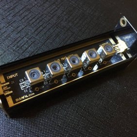
This is a Built & Tested unit, complete and encased into an RF-tight Aluminum Box
2.5 KV and 3KV NPO Capacitors
High Power Toroids
Good up to 54 MHZ
0.4 dB max loss on 160m band, -80 dBc @ 1 MHZ
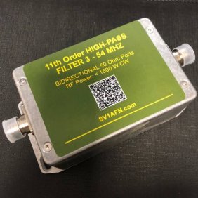
This design is a 11th order Tchebyshev high-pass filter with very low ripple.
This filter is offered in two variations, one low-power, for receive only applications and another capable of withstanding high power, i.e., capable to pass high power on all HF bands including 50 MHZ without the need to put it out of the line when transmitting up to 1500 W or more.
There is no something high-tech on these filters, only, because many friends of mine were not satisfied from the performance of commercial low cost similar filters, asked me to develop a better one with more elements to give rapid attenuation of the MW BC band of 550 - 1600 kHZ, while to perform transparently on all of the rest of the HF spectrum with minimum loss. I have started the design thinking to sacrifice the 1.8 - 2.0 MHZ amateur band (or, at least don't care about this band) because I didn't know how to get minimal loss on 160 m and deep attenuation on the area of 550 - 1600 kHZ at the same time. One solution was to use an elliptic design which provides rapid attenuation curve but only up to around -40 dB minimum attenuation of the rejected band so to be practical and easily reproducible, and another solution was to use high-order and carefully selected good components with the Chebyshev coefficients. With the chosen topology, an attenuation curve of around 10 dB per 100 kHZ has been achieved, -13 dBc on 1600 KHZ, (-20 for some prototypes), -26 dBc on 1500 kHZ, - 37 dBc on 1400... <-100 dBc under 800 kHZ and even more on 550 kHZ., while its maximum loss over the 1.8 to 54 MHZ range is on the middle of the 160m band with 0.4 dB, which is quite acceptable at low power levels, while its maximum loss over the 1.8 to 54 MHZ range is on the middle of the 160m band with 0.4 dB, which is quite acceptable at high power levels. The insertion loss at 30 MHZ is also 0.4 dB and it is flat to 54 MHZ.
USE: Insert the filter between the antenna and the transceiver. You will notice immediate signal to noise ratio improvement since the strong broadcasters will be eliminated. Also, the filter will severely attenuate all low frequency interference from solar-panels, inverters, high-voltage sources, the reception performance will be greatly improvise.


Normal operation with temperature around 64 C is with 1500 W (CW) at 10 and 28 MHZ. Damage level was reached when increased power to 2100 W (CW) at 3.5 MHZ with high VSWR. The output caps failed (C11, C12)