
ADL5519 RF Power Detector
1 MHZ to 10 GHZ, 60 dB range Dual Channel
With Ultra-Low-Noise Voltage Regulator
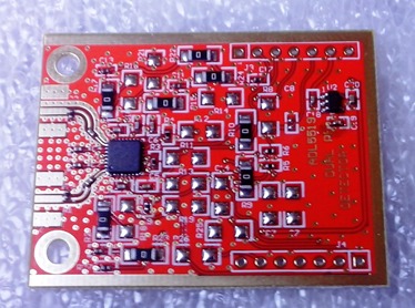
Based on the Analog Devices ADL5519 chip, this module is a complete Dual channel RF Power meter head for 50 ohm systems
working from 1 MHZ to 10 GHZ with 62 dB dynamic range (+/- 3 dB).
For both RF channels, the RF input SMAs are terminated to a 52.3 - 0.1% Ohms resistor (R2 and R1) to match the ADL5519 input resistance to 50 Ohms.
It draws 60 mA at 12 VDC and has an on board 5V voltage regulator.
For low noise operation, a special ultra low-noise 5 V voltage regulator is used. The LP2985AIM5-5.0 is made by Texas Instruments and is optimized for RF circuits. This one powers the ADL5519 chip. Its input can be connected to an external power supply of +5.25 min to 16V max via edge connector J3, pin 6.
The ADL5519 output voltage is routed to the same connector (J3) pin 5 for RF Channel A and pin 4 for RF Channel B for 22mV/dB measurements.
All of the scaling resistors as described in it's datasheet are in purpose large (of 1206 SMD size), in order to facilitate hand soldering/de-soldering if any change is required..
The PCB dimensions are 46.5 x 36 mm and a special gold-plated band is provided on the edges to help soldering any shielding material (copper clad board, tin etc).
Being dual channel aids in direct Return Loss measurement and it is mostly suited for VSWR (FWD/RFL power) measurements, but it sure can be used as a general purpose power meter with an incredibly large frequency range. I encourage you to study the datasheet. It contains temperature output, inverted outputs and much more that will trigger your imagination for your future project.