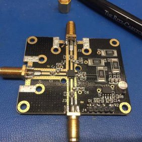
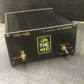
ORDERING: Both complete, encased & tested and PCB modules without enclosure and connectors are available. Choose the variation you need.
Attention: If you want manual control you will need to make a small box with a toggle or rotary switch to send 3.3 or 5V to S1 or to S2 relay select inputs. We offer a similar control box separately.
This is a high-power RF switch with remote control input, made with minimum-losses relays and it can be used to switch between 2 different antenna systems for a transceiver, or between 2 different radio transceivers for a single antenna system.
Indicators: 3 mm green LED indicator to show which port is connected
Relay drivers on-board, it can be controlled by any GPIO, output pin of any microcontroller, Arduino, Pi, ESP-32, Bluetooth device or Wifi or GSM/4G/5G switch for remote applications.
Connections: S1 and S2 input pins if get a HIGH (3.3V or 5V) will energize the corresponding relay. Deactivation is done by stopping the application of the input signal. G is the Ground (0V) connection and + is the plus connection of the 12VDC power supply.
DC Power: 12VDC, 40 mA - If the unit is not powered with DC power or no inputs selected, the relays connect the RF ports to Ground
Dimensions: 111 x 67 x 37 mm die-cast Aluminum Box painted Grey (98 x 52 mm for the PCB module)
RF Power handling: 1500 W - Not suitable for "hot switching", i.e., stop transmitting, then switch.
Insertion loss up to 70 MHZ: < 0.1 dB
Insertion loss at 145 MHZ: <0.12 dB
Isolation between ports: > 50 dB @ <30 MHZ - Decreases at higher frequencies
RF Connectors: SO-239 (N-type on special order)


