


OLED Controller MCU for 1 or 2 RF Step Attenuators SPI Modules
NEW: With Arduino Nano and 1.3" OLED
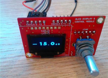
This small PCB (61 x 35 mm) incorporates an MCU (PIC24FJ32GA104), a rotary encoder, a 3.3V voltage regulator, a 0.96" OLED and 2 connectors for connecting 2 RF attenuator modules (see above).
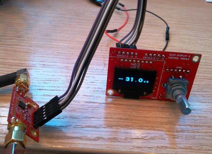
The idea is to make an independent digital RF attenuator with it's own user interface.
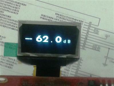
The MCU supports 0-31 dB control range with one RF attenuator module, or 0-62 dB control range with 2 RF attenuator modules. This is selectable with jumper J5. Upon power-on, it starts at 0 dB. Then the rotary encoder controls the attenuation value, the MCU controls the PE4306 chip of the displayed value and then stops sending data in order to reduce any RFI to other circuits. The push-button, inside the rotary encoder, changes between 1 dB or 10 dB steps.
J1 is for the 5V DC input.
J2 and J3 connect to one or two series connected RF step Attenuator Modules. They carry the SPI bus plus the 3V DC power for the RF Step Attenuator Modules.
J4 is the ISP connector
The rotary encoder and the OLED are mounted on the bottom side of the PCB. A special double sided thick label is provided to protect the OLED.
The RF step Attenuator PCB Modules are sold seperately.
