


Miniature HF Band-Pass Filter (Built & Tested PCB Module)
- 5% 0402 or 0603 NPO Capacitors
- Adjustable inductors
- Available for all individual HF amateur bands
- 36.7 x 14.2 mm small PCB
These filters are of the same design as used in my Ham-Bands Preselector, but many friends emailed me to make individual single-band filters to be placed into their own projects of receivers, single or dual or triple band transceivers etc., where the preselector board is so large to fit, or expensive since it has all those relays. While the design is simple, offering those mini filters requires a lot of work, but it has been done already and we are able to serve those needs and we now have them available for shipping.
A miniature high-quality PCB has been produced, the capacitors and special inductors have been ordered and some DIY KITs are now ready. Each of them has a unique code number to help us keeping track of the inventory of the components and ensure error avoidance. There are 9 filters available, one for each of the Amateur Radio HF bands and a 10th is getting ready for the new 5 MHZ band. Each of them is offered as a DIY KIT or ready-made and tested. They can be used in receiver input stages, before a preamp and maybe a second after the preamp, to make switched preselectors or multiplexers. They can only work with low-level transmit applications at mW level to clean up VFOs, mixers before a power amplifier, for experiments and measurements. Especially cleaning RF signal generators for IMD measurements.
Aligning the filter is very easy, by adjusting the two variable inductors with a ceramic or plastic slot-tip screwdriver.
Please leave a note when at check-out to indicate the band (frequency range) you need the filter to be.
Available bands:
6m/10m/12m/15m/17m/20m/30m/40m/60m/80m/160m
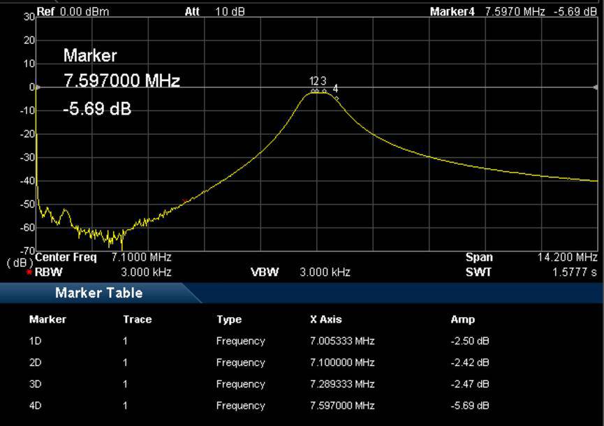
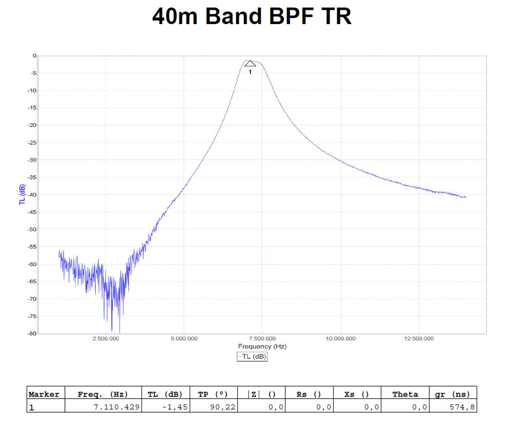
Fig. 1. The frequency response of a prototype built for the 40-meter band The plot is available by pressing the red button.
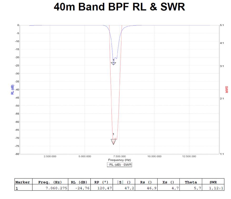
Fig. 2. The Return Loss plot over the 40-meter band of the same prototype, including SWR plot The plot is available by pressing the red button.
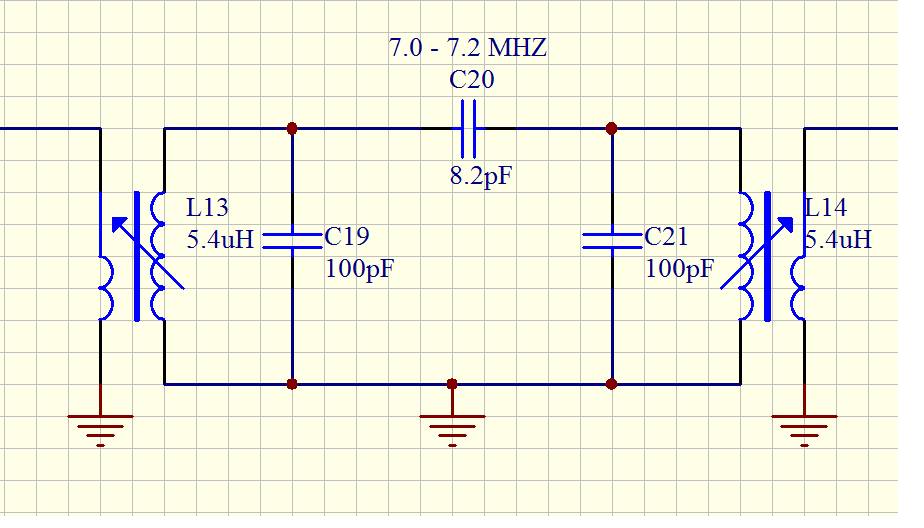
Fig. 3. The Schematic Diagram of the filter showing part values. A document with all the filter schematics is available by pressing the red button.
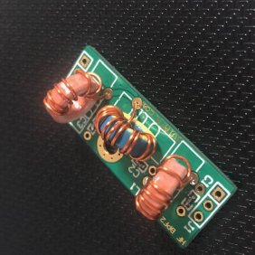
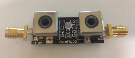
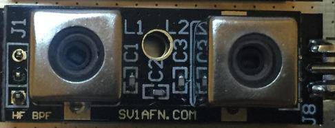
Photo 1 & Photo 2. The PCB is of highest quality, with 1-oz copper layers, gold plated and 0.8 mm thick FR4 but minimal in size so to be able to fit into your project. Between the two variable inductors there is a 3 mm hole for a supporting screw. The input and output ports have three 2.54mm spaced pads with holes, so ordinary pin-headers can be used for mounting them.
Photo 3. A photo of the frequency response on a spectrum analyzer with tracking generator.
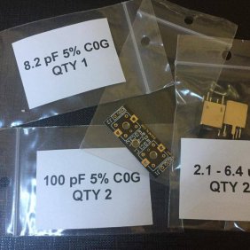
Photo 4. A photo of the 40 -meter band DIY KIT as prepared for shipping
We offer the same product as a DIY KIT with soldered capacitors, the buyer solders and tunes the inductors.