
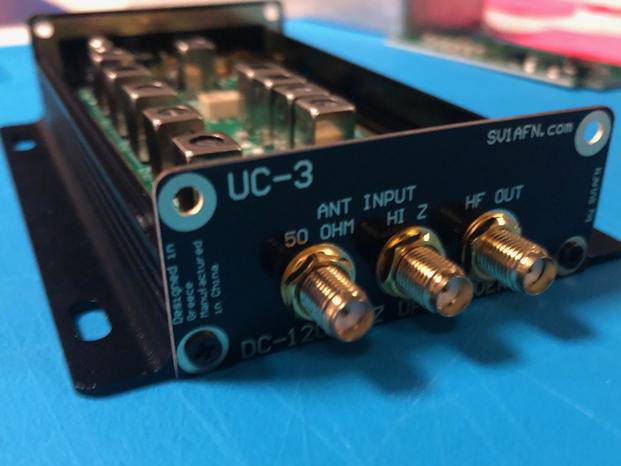


VLF/LF Up-Converter for SDR or Analog Receivers DC-120 KHZ
Built & tested PCB Module encased into a 110x63x25 mm Aluminum enclosure
-
With Gas Plasma Discharge Tube for overvoltage protection on both 50 Ohm and Hi-Z Antenna inputs
-
With Diplexer filter before the mixer
-
With wideband amplifier after the mixer
-
High Stability 10 MHZ TCXO & External LO input
Most good HF receivers, unfortunately have poor performance on Low and Very Low Frequencies (LF/VLF). This is because of many reasons including designer's attention, cost issues, synthesizer phase noise, linearity of front-end etc. The idea here with this upconverter is to use a good HF receiver to copy 0-120 KHZ at 10.000-10.120 MHZ (or 0-520 KHZ at 10.000-10.520 MHZ for the 520 KHZ model). The benefit is that the user enjoys his good HF receiver features receiving the VLF/LF band with a much better performance on a higher frequency. For the newcomer to lower frequencies, a whole new world is there to explore!
The output signal of a very low-phase-noise and high-stability TCXO working at 10 MHZ is used as a carrier to move the incoming spectrum of 0-120 KHZ to 10.000-10.120 MHZ. This is done with a double-balanced RF mixer, again with its IF port wired as an input just like in my first SV1AFN's Upconverter for HF with 200 MHZ LO.
For connecting an antenna directly to the unit, special Gas-Discharge Tubes are included in the design to protect from overvoltages and because a 50 Ohm input is considered to be of little use, a second antenna input has been added with the use of a 16:1 BALUN transformer made by Mini-Circuits with guarranteed specifications. This allows a HI-Z antenna input port to be added, which is more desirable for long-wire types of antennae. The bad news with the BALUN transformer is that its frequency response starts at 30 KHZ instead of 0 HZ. As we have tested, the device is still usable at even lower frequencies but with rapidly increasing attenuation as the frequency goes lower.
The antenna input, before applied to the mixer's IF port, passes through a diplexer filter with a 9th order high-pass and a 9th order low-pass section. The high-pass section is terminated into a 50 Ohm resistive load so all RF energy collected from the antenna above 120 KHZ (or 520 KHZ), which happens to contain all strong MF broadcasters in addition to million others, will get burnt into the resistive load and don't be reflected back and forth betweeen the antenna and the mixer. The low-pass section goes to the mixer to be upconverted to 10 MHZ. This arrangement adds to the dynamic range and it worths the effort, instead of simply using a low-pass filter. For the DC-120 KHZ model, the diplexer filter cross-over is at 120 KHZ and for the DC-520 KHZ model the diplexer filter cross-over is at 520 KHZ.
The up-converted signal appears at the RF port of the mixer and is applied directly to a wideband amplifier (GALI-74+) for terminating the mixer corrrectly. This amplifier overcomes the mixer's and diplexer filter's losses and adds some gain more. If this extra gain is not desired, an attenuator can be employed at the user's HF receiver.
DC power for the 10 MHZ Local Oscillator and the wideband amplifer comes from the mini-USB connector. A special common-mode noise rejection filter eliminates any computer noise and provides a clean supply of DC. It is not over-engineered, if you quickly see the 6A fuse and heavy gauge wire. It is because the ground of a user can be poor and some voltage difference can be developed between the antenna and power (computer) ground. This makes the ground current to increase. Exactly the same circuit was used in one of the first upgrades made for the Encased SV1AFN's HF Up-Converter. The board outputs 5VDC for an external GPS Disciplined Oscillator, like the SV1AFN's GPSDO-2, so to stop using the internal TCXO and use the externally applied 10 MHZ signal to J4 SMA connector marked as "EXT LO" if the LO's drift/accuracy is of great importance to your applications. In this case, JP2 should be removed so to stop powering the internal TCXO with DC power. The same SMA connector, outputting the 5VDC can be used to input 5V DC from an external clean power supply if using the USB connector is not desirable.
Choice of output IF at 10 MHZ: Since the design after the mixer is wideband, any frequency can be used. If a user cannot use 10 MHZ, the internal TCXO can be easily changed to another frequency, anything from 0.5 - 500 MHZ. The upconverted VLF/LF signals will be moved to that frequency since the mixer's LO/RF ports work from 0.5 to 500 MHZ and the wideband amplifier (GALI-74+) works from DC to 1 GHZ.
Jumper JP1: Users can use this connection to feed a sound-card, or anything else. This is the reason for JP1's presence. It provides a well filtered spectrum of DC-120 KHZ (or DC-520 KHZ) to be used by any external device or system.
L10, C24 and C25: The inductor L10 in series with C24 form a series tuned network which converts the square wave of the 10 MHZ TCXO to sine. The converted sinewave feeds the mixer. If a user wants to experiment with feeding the mixer with square wave (because the internal diodes conduct for a longer time...and this improves IMD performance), then he needs to place a high capacitance capacitor, like 100 nF, in the place of C25 which is now empty, so to bypass the tuned network. The same can be done if the user will change the TCXO for another LO frequency. Then, L10 and C24 should be changed to tune on the new frequency or C25 should be fitted to bypass the tuned network.
The schematic diagram is provided as a PDF file above.

