


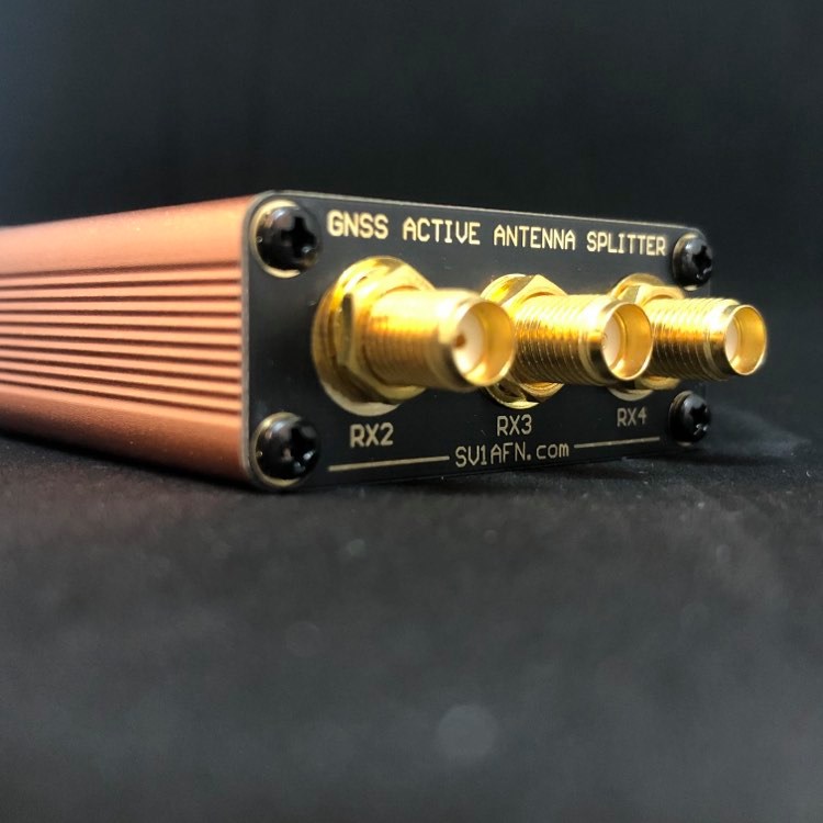


GPS Antenna Splitter (Built & Tested Unit)
-
50 Ohms in/out SMA ports
-
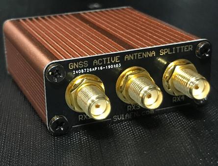
4 Output Ports
-
For Passive or Active GPS Antenna
-
Supplied encased, built & tested
-
Works with 3.3 or 5 VDC receivers
The GPS signal is very weak at the Earth's surface. It is actually under the noise (KTB). The GPS signals are usually specified at -165 dBW (-135 dBm approx 0.035 uV)!
Thermal noise (KTB) in a receiver's bandwidth of 9 MHZ however, is -104.46 dBm. The receiver works nicely at a -30.5 dB RF input signal to noise ratio! How this happens? Well, the GPS is a direct-sequence system with 10.23 Mcps code rate, 9 MHZ RF bandwidth and 50 bps data rate. Its "process gain" is approximately
9 x 10^6
10 log ----------------- = 52.5 dB
50
So, a GPS receiver takes a negative input S/N ratio of -30.5 dB and produces a positive S/N ratio of 22 dB (= 52.5 - 30.5).
Magic!
Now, 22 dB S/N ratio is adequate for most transmissions, but if there are obstacles between the antenna and the sky, long antenna cables which add losses or over-amplified LNAs and active antennas are placed in a system or at an installation, then a very bad RF front-end can be produced, which can also amplify nearby cell-phone or cell-tower signals, broadcasts of any kind, including WiFi etc. and degrade the S/N ratio so much and make impossible to detect GPS signals.
The above is true for the military version, the commercial GPS at L1 is 1 MHZ wide instead of 9 MHZ, but the concept is similar.
The GPS antenna-splitter presented here is designed to allow one GPS antenna to feed 1 up to 4 GPS receivers. The RF splitter used is passive and has 6.7 dB theoretical loss. A very low noise amplifier is used ahead of that splitter to overcome splitter's loss and still provide some more gain to equalize for any cable losses. The amplifier's gain is 18.5 dB and its noise figure is 0.55 dB. But simply placing just this amplifier ahead of a splitter would not make a nice GPS splitter so easily. All interfering signals would have been amplified together and finally would have mask the wanted weak one. This design uses one bandpass filter up front the antenna input, before the LNA, and a second identical filter after the LNA. The filter's insertion loss is 1.5 dB each and the overall cascaded gain is 8.5 dB and Noise Figure 2.37 dB. The filters loss in the center frequency is 1.1 db and this makes the cascaded gain 9.3 dB and NF 1.92 dB.
The RF splitter's loss is calculated at 7 dB.
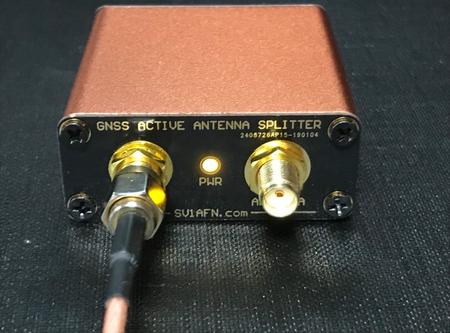
Another feature of this design is that it allows active GPS antennas to be connected, meaning the DC power coming from a GPS receiver will be used to power the antenna and the GPS splitter itself. Just, this receiver should be connected to J2. The rest 3 output ports are equipped with 220 Ohm resistors (a 22.7 mA load at 5VDC) through RF chokes. This will alllow the connected receiver to believe it has not lost his antenna because most receivers are equipped with a current sensor so they can detect a broken antenna cable. So, to avoid false alarms, this splitter allows the connected receiver to detect this current flow and work properly without alerting a user or a system about a fault which does not exist.
A small LED lights when a GPS receiver is connected in J2 with DC power enabled at it's antenna port. This is normal for feeding an active GPS antenna. The antenna connects to J1 and takes this DC current normally. Just in the case the GPS antenna is passive, still it can be connected to J1 but the user should apply 5VDC to J2 for the splitter to operate. Or, activate the DC power at the antenna post for the GPS receiver which will be connected to J2.
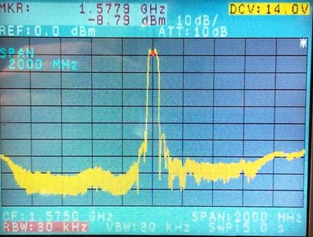
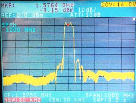
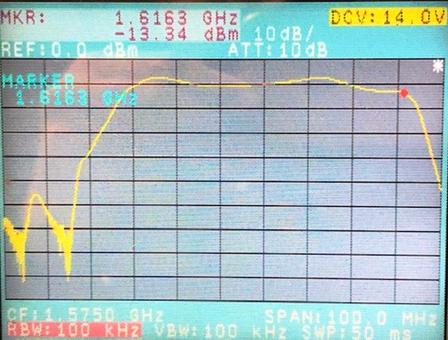
The band-pass filters used are wide enough to let this splitter work with all frequency channels assigned for commercial use (GPS at 1575.42 MHZ, Beidou at 1561.098 MHZ, GLONASS at 1602 MHZ center frequency and Galileo at 1575.42 +/- 12.3 MHZ.
Here is a plot of the passband: