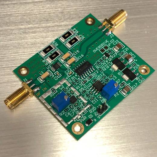
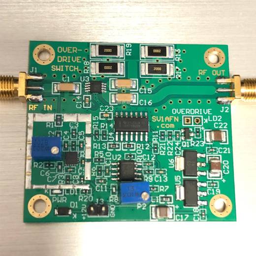


RF Amplifier's
Input Power Over-Drive Switch (NEW VERSION)
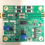
(Factory assembled PCB module)
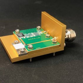
- 50 Ohms in/out SMA ports
- HMC784 RF Switch
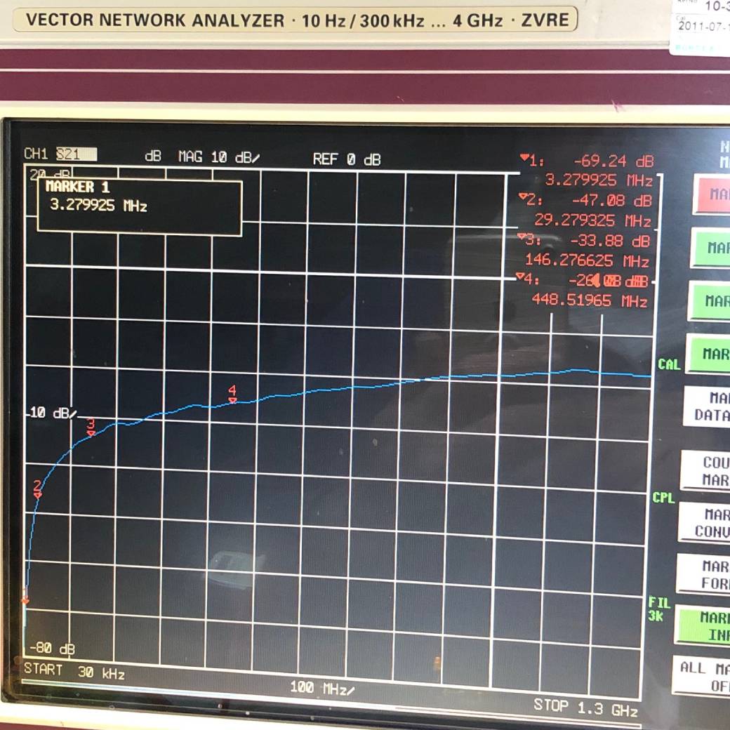
- 1 MHZ - >1 GHZ
- -30.....+40 dBm RF power input - 10 Watts max
- 30 dB isolation if the input power exceeds the preset threshold
- 12 W / 50 Ohm load resistor to dissipate the input power
I have received some emails from friends asking if we have anything available for protecting expensive RF Power LDMOS transistors because they can easiy be destroyed with excessive input power.
Here is a wideband solution (LF to >1 GHZ) which uses an RF Switch. The input signal goes normally to the output connector and only gets the insertion loss of the RF switch (0.15 dB at 30 MHZ...under 1 dB at 1 GHZ). The input signal is sampled with a log-amp circuit based on the Analog Devices ADL5513, (super fast like a diode) and this monitors the input power continuously. Its output voltage, if below a preset threshold, allows for the input signal to be applied to the output connector directly without any loss except this caused by the RF switch. But if above a threshold, the voltage comparator drives the switch in order to connect the input signal to four 200 Ohm / 3-W resistors which make a 50 Ohm dummy load. The input of the expensive amplifier is protected by the isolation of the switch (around 20 dB minimum, at high frequencies, much more (35 to 75 dB at HF and VHF). This lasts as long as the input signal is above the threshold. When the input power gets below the threshold it is driven to the output port again.
The device can work with a receiver input, or a spectrum analyzer input or SDR so to protect the front-end from overloading.
The new version of the RF Power Overdrive Protection Switch module only needs +12 VDC (50 mA) for its operation as it now has all lower voltages generated on-board with voltage regulators.
LD2 is an output for an external LED if the user needs a visual indication of the overloading.
More uses are possible, like for a modulator, clipper etc.
PCB dimensions: 47 x 53 mm