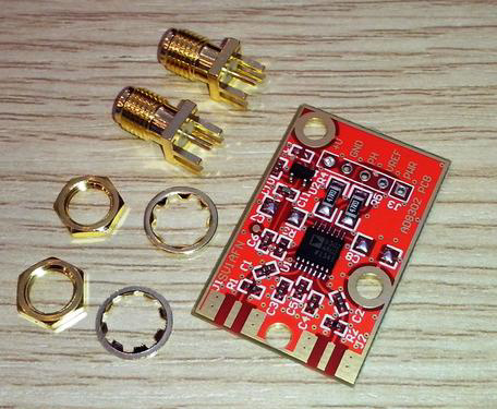


AD8302 RF Power & Phase Detector (Factory Built & Tested PCB Module)
The PCB Module includes a high-quality ENIG FR4 PCB (33.4 x 21.8 mm) that comes with all SMD components factory pre-soldered. .
LF to more than 2700 MHZ (2.7 GHZ) Power and Phase Detector
With Ultra-Low-Noise Voltage Regulator
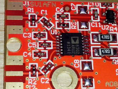
Based on the Analog Devices AD8302ARU chip, this small module is a complete RF Power difference and Phase Difference detector for 50 ohm systems working from below 1 MHZ to more than 2700 MHZ with 60 dB dynamic range (-60 to 0 dBm).
The RF input SMAs are terminated to 52.3 Ohms 1% resistors (R1 and R2) to match the AD8302 input resistance to 50 Ohms.
It draws under 20 mA at 12 VDC and has an on board 5V voltage regulator .
For low noise operation, a special ultra low-noise 5 V voltage regulator is used. The LP2985AIM5-5.0 is made by Texas Instruments and is optimized for RF circuits. This one powers the AD8302ARU chip. Its input can be connected to an external power supply of +5.25 min to 16V max via edge connector pin 5.
The AD8302 chip has two outputs of interest. The first one indicates the power difference of the two applied RF signals and produces a voltage to represent a -30 .... +30 dB difference with a 30mV/dB slope. The second is the Phase output that indicates the phase relationship between the two RF input signals with a range of 30 mV to 1.8 V. For a degree change, the output changes 10mV. These outputs are routed to connector pins 1 and 3 via a 47 ohms resistor in series. Both outputs can source/sink 8 mA and are very fast (30 MHZ envelop bandwidth). Please consult the datasheet for a better explanation. There is an internally generated voltage reference of 1.8V and is routed to pin 2. If ever needed please remember it can source way under 5mA, actually sourcing 5mA produces a 1% voltage drop. Pin 4 is the Ground pin and pin 5 the positive power supply input. AD8302's pin 8 and 14 are left unconnected but there is space for placing 2 small caps for filtering if needed, these are C7 and C8.
The PCB dimensions are only 33.4 x 21.8 mm and a special gold-plated band is provided on the edges to help soldering any shielding material (copper clad board, tin etc).