


AD8318 Digital RF Power Detector (Built & Tested PCB Module)
With 12-bit ADC (SPI interface) and ultra stable Vref, Ultra-Low-Noise Voltage Regulator and analog 24 mV/dB Output
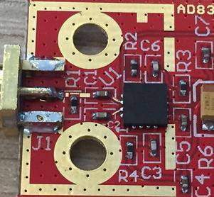
Based on the Analog Devices AD8318 ACPZ chip, this module is a complete RF Power meter head for 50 ohm systems
working from very low frequencies (1 MHZ) to more than 6000 MHZ (up to 8 GHZ). Its dynamic range is from -65 to 0 dBm, or better with more error.
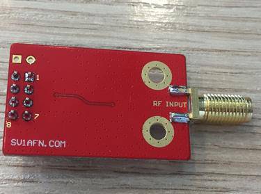
The RF input SMA is terminated to a 52.3 - 1% Ohms resistor (R1) to match the AD8318 input resistance to 50 Ohms.
It works from 6.5 to 16 VDC (it draws 60 mA at 12 VDC) and has an RF optimized ultra low noise voltage regulator to supply 5 V DC to the circuit.
The AD8318 output voltage is routed to the output connector pin 8 for 24mV/dB analog measurements but also to the AD7887BRZ 12-bit Analog-to-Digital converter's input. Notice the B version of the ADC chip is better than the A version, and almost double the price. The 2.5 V Voltage Reference IC used is the ADR421BRZ, again the B version is used instead of the A version. This is because it offers 1-3 ppm/C instead of 3-10 ppm/C of the A version. B version's accuracy is +/- 2 mV instead of +/- 6 mV of the A version's. Now, an Arduino or similar MCU with an SPI interface can benefit of the better accuracy and resolution available on the board of the AD8318 Module and make a much more accurate power measurement.
The AD8318 has a temperature reading output which is also routed to the output connector (pin 4).
The PCB dimensions are 22 x 34.5 mm.
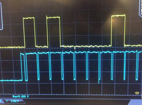
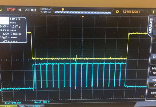
Ph.1. Sending 10100001 to AD7887 (control byte to select external Vref and the AIN0 input). The yellow trace is the MOSI and the blue one is the clock
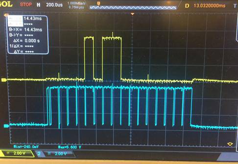
Ph.2. The yellow trace shows the CS (low to activate the ADC) and the blue trace shows the clock as output from an MCU. 18 transitions are enough for sending out 8 bits, for the control byte, and reading 12 bits, the conversion value, plus its 4 heading zeros.
Ph.3. MISO signal (yellow) as sent from AD7887, the first 4 bits are always 0s, then the rest 12 bit ADC value is shifted out. The value is 2.1V (AD8318 at noise level). Remember AD8318's slope is negative, -25 mV/dB. The blue trace is the clock signal.
Until today I couldn't use the Arduino SPI library. The AD7887 starts sending the 12 bit value while Arduino is still outputing the 4th bit of the control byte. Study the AD7887 datasheet to see.
With the Arduino SPI library, there is a command for writing to the slave and another command for reading from it. But I couldn't figure out how to read and write simultaneously. So the code is "hard-coded" with LOWs and HIGHs to send/read data on rising and falling clock edges.
I put it here to help anyone who would like to play with it. It is not a completed power meter yet, but because it was not very easy for me, I thought this can help others to start.
The code sends the ADC control byte, reads the measurement from the AD7887B ADC, converts to dBm and measures the AD8318 chip temperature. It then averages the result of 100 readings and display it on the serial terminal.
It still needs a way of calibrating and a way to correlate the log-amp's temperature with the reading. And of course to drive a nice display.
VIDEO AVAILABLE
Watch this small video from my new youtube channel. It shows Dietmar's (DL2SBA) amazing implementation for a "simple" RF power meter built with an Arduino. Here is his website.
The power meter has now finished and features a great calibration process.
It makes an amazing power meter!
With some Arduino boards, an unstable operation of the CS pin has been noticed. A solution is to add a 4.7K - 10 K resistor in series with the CS pin from the Arduino output to the module's CS input.