

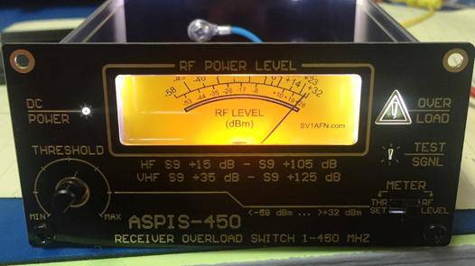


ASPIS-450
Receiver Overload Protection Switch (Built & Tested)
ATTENTION: OUT RF STOCK!
- 10 KHZ - 450 MHZ
- Very Low Loss Directional Coupler
- RF Power meter based on fast AD8310 Log-amp
- PIN diode for instant protection and receiver port grounding through a relay
- Adjustable setpoint
- Built-In-Test Oscillator
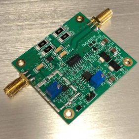
This miniature (100 x 100 x 50 mm) module comes completely factory soldered and tested.
It is based on the Analog Devices AD8310 fast log-amp and on a Mini-Circuits signal-tap (directional coupler)
Its major features and benefits include:
Antenna input port - Receiver output port impedance: 50 Ohms
Extremely low loss (0.12 dB at lower frequencies through VHF, 0.4 dB max at 450 MHZ)
Max input RF power level: 1 Watt CW or 12 W pulse
Supply current: 250 mA max at a supply voltage of 12-18 V
ESD supressors both at Antenna and Receiver Ports (100 V trip voltage)
Plasma Gas Discharge tube 70V at the Antenna input port
Directional Coupler from the Antenna input to the Receiver output offering galvanic isolation
True RF power meter with 90 dB dynamic range and super fast (20 ns) response
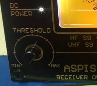
Front panel adjustable threshold (set-point) of the power level desired to enable receiver protection
12 W PIN diode across the Receiver port for immediate protection
Optional receiver port grounding through an RF Relay contact (remove jumper to disable this option)
Internal 10 MHZ test oscillator for system check
Event counter output (TTL) for system logging
Set and forget device. Protect your precious receiver from nearby static discharges, high-power narrow-band and wide-band sources, transmitters, generators etc. As soon as the antenna input power increases your receiver input will get grounded for as long the input level is above the setpoint.
Deluxe protection of your receiver system plus a bonus accurate power meter
Only expensive receivers and spectrum analyzers are equipped with an overvoltage protection circuit and in most cases they offer a limited set of functions in order to keep costs down and to avoid extra signal losses at their input. But, co-location of many different systems may increase the risk of exposing a sensitive receiver's front-end to a dangerous voltage level which can harm or damage it. If the damage is severe, the operator can notice and take care of it but if the damage is for example a 10 dB loss of sensitivity or similar, the user may never find-out!
With the above thoughts I made up with the project described here. In the beginning, a very nice directional coupler was found from Mini-Circuits. The ADCB-20-82+ is used firstly to offer galvanic isolation through its built-in transformers and secondly as a signal tap, using its coupled -20 dB port to measure the power passing from the input to the output. The forward coupled port is connected to a fast (very fast, like a diode detector) log-amp made by Analog Devices, the AD8310. This chip can measure down to -78 dBm from LF to 450 MHZ and since the 20 dB coupling loss, we can have a measurement range from -58 to + 32 dBm (90 dB range).
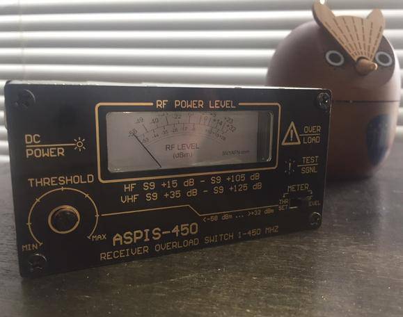
Now, -58 dBm means S9 +15 dB to a shortwave listener or S9 +35 dB to a V/UHF receiver's s-meter, because the signal strength "S-scale" is defined for -73 dBm for S9 and 6 dB per S-unit / add -20 dB for V/UHF. I suppose that any receiver can handle S9 +15 dB without needing any protection and this fits our -58 to +32 dBm range very nicely. The log-amp output voltage is applied to a fast voltage comparator (the old LM311 but now much faster as -EP Enhanced Product) and causes its output to go logic LOW if it exceeds the reference voltage applied to its reference input. The reference voltage is made variable with the use of a front-panel placed trimpot. All of the above, without an indicator device would be hard to adjust by converting dBms to Volts etc, so a DC amplifier opamp has been added to convert the 24 mV/dB of the AD8310's output to 100mV/dB and drive a moving-coil needle meter used as a voltmeter to display both the threshold ref voltage or the actual log-amp's voltage as selected with a front-panel switch on an rf power scale. I owe the reader an explanation: The voltage is what we need to measure at a receiver's input. But the log-amp converts the voltage to power, so we can talk about power and do the calculations with dBm (dB referenced to 50 Ohm milliwatt). S9 on the S-meter scale means 50 uV or -73 dBm. Now, the user can set a threshold voltage, displayed as a power level on the needle meter scale and if the input gets higher than this it will couse the output to go LOW.
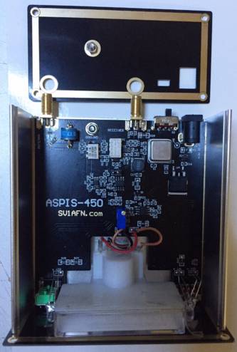
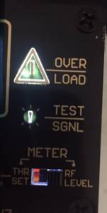
What can now be done if the comparator's output goes LOW: First, you can count how many times it went low over a time period, this can help you to see that your site is not or it is problematic or constitutes a difficulty. The unit described here provides just the output on the comparator's output pin and you may need a datalogger, a computer or an Arduino etc to make this. Second, the receiver can be immediately protected with the use of a shunt-connected PIN diode. The PIN diode used is a modern SKYWORKS SMP1302-085LF and it is biased at 100 mA. As used here, it offers 40 dB receiver isolation (goes lower as the frequency increases) and as soon as the relay contact closes in about 10 msec, it handles all excess input power. When the relay gets energized the receiver port is shorted to ground. This offers about 50 dB of isolation (again, it goes lower as the frequency increases). At the same time, an "overload" LED indicator displays the event on the front panel. As soon as the input level goes lower than the setpoint, the comparator's output returns to logic HIGH, the relay is de-energized, the PIN diode gets dissappeared from the line.
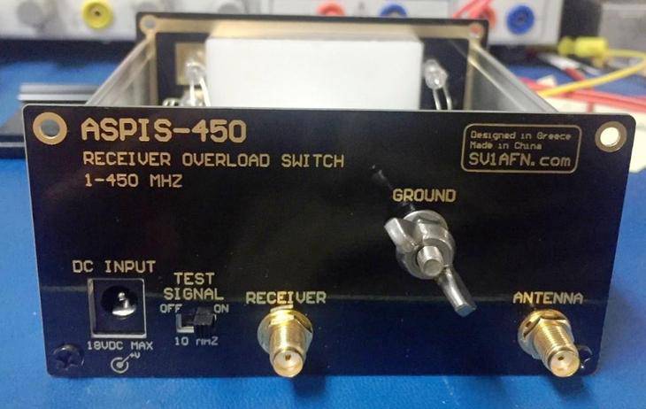
In order to increase user's confidence that the system operates normally, into my mind this unit is a set and forget device, I have added a test oscillator which is always off. When powered up, using a slide switch on the rear panel, it produces a strong test signal at -11 dBm on 10 MHZ which is applied on the directional coupler's reverse coupled port. Remember, a directional coupler's ports are bidirectional, so the test signal now appears on the line for measurement and for detecting on the connected receiver if the threshold is set lower than -11 dBm. The user can check if the switch works at any time, by adjusting the setpoint. Using a receiver's attenuators one can also check if the sensitivity of the receiver is ok or it has been changed!
The ASPIS-450 receiver protection unit does not protect a receiver or the unit itself from a direct or indirect lightning strike and by no means I accept any liabiliy. The unit is equipped with a Plasma-gas discharge tube and 100V ESD protection devices, which is very good and welcome if your receiver doesn't have any, and grounding the screw provided on the box improves its ability to keep your receiver healthy inside a hostile environment. Adding surge protectors on the antenna line adds to safety. Because the reaction time of the unit is sub microsecond this design can offer best protection against distant strikes which otherwise would have caused damages. Older designs with lamps, bulbs and fuses are much slower to break so to actually protect. The front panel meter is a nice addition, if one day you see large readings, disconnect your antennae and don't operate. If your system is near to high power generators, other transmitters etc. yes, the unit can protect your receiver, again within limits. But high power interference and lightning strikes are totaly different matter and the reader should have been warned.
BONUS RF POWER-METER: If you apply a signal from the Antenna port, the power meter will tell you its power level on the analog meter. The power meter's dynamic range is huge (90 dB) and the meter's scale is small, so small changes cannot be measured easily. As it comes, the power meter accuracy is factory adjusted on 450 MHZ. I will post correction charts below soon for measuring on 10 MHZ and on 100 MHZ. Generally, it shows higher power on lower frequencies and it needs a correction chart. But if you need to adjust a filter or an amplifier or tune anything, sure it can be used as a normal power meter.
As it is now, the power meter is a wideband power meter, the displayed power level is of a signal that is >450 MHZ wide. This is how it's supposed to be, so the receiver can be a wideband one. But you can connect an external filter to get more accurate readings about a specific frequency range for example. Adding a 30 MHZ low-pass filter will make the meter respond only up to 30 MHZ. Or connecting the power meter to a receiver's filtered IF output will make a nice S-meter.
You can also use ASPIS-450 as a frequency trap. For example, you can place a band-pass filter centered on any frequency, prior to the unit. When a signal appears emitting on this frequency and its signal strength is above the setpoint, you can get a notification delayed only by the filter group delay and the total system's reaction time.
If you are watching my projects for some time, you may know I like working on the PCBs. This time I discovered a new "patent". Making enclosure panels from PCB material is not new, but removing the copper from the bottom layer, adding a graphic on the top layer and playing with the mask and paste layers, attractive indicators can be produced.