


Attention: OUT OF STOCK!
H-Mode Mixer Module
- as per PA3AKE description
- With DAC or Potentiometer for bias control
- With DAC or Potentiometer for LO wave symmetry
This is a DIY KIT
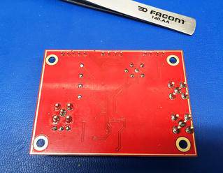
The KIT includes a high-quality ENIG FR4 PCB (63.5 x 46.7 mm) that comes with all SMD components factory soldered.
RF capacitors are used for all the circuits. Three SMA female connectors of the vertical mount type are also supplied together with 3 pcs BN43-2402, some 0.25 mm wire, 2 trimmer pots and 2 jumpers.
During the last 5 years I have built more than 15 units of these RF mixers, for friends and myself, using my hands only, on pieces of double-sided copper clad boards and "ugly" construction methods. Every time I had one finished, I was staying late in the lab measuring and checking possible improvements. If to increase LO power (voltage), how to have the best symmetry all the times, how to adjust the bias independently of the frequency range, how to extend the frequency range, etc. That last phone-call a couple of months ago, asking for another one, made me decide to finally prepare a small PCB this time and thus eliminate the need for making another one from the scratch again. I haven't made the PCB before, because I was thinking I have nothing to add or modify as this is great already! These people (G3SBI, PA3AKE) have offered Amateur Radio with an important advancement. For those who cannot fully understand the meaning of IPO3 and IMD figues on a mixer, I have shot a photo of a SBL-1 mixer's IF output spectrum using the same test setup as with the h-mode mixer just to compare it visually.
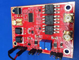
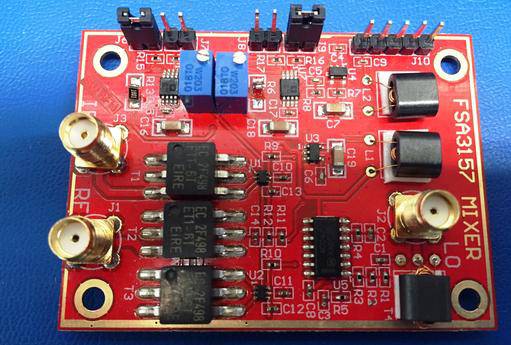
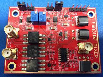
The PCB dimensions are 46.7 x 63.5 mm and all SMD components are factory soldered.
L1, L2, L3, P1, P2 and the SMA connectors are not soldered in place.
L1 and L2 are wound with 6-turns of 0.25 mm copper enameled wire on a BN43-2402. They make a choke of about 50 uH and they filter DC power as produced by the two Micrel voltage regulators. One is fixed for 5V and the second is adjustable, set at 7V with R7 and R8.
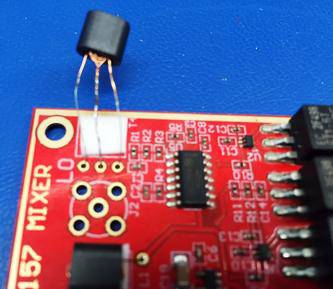
L3 needs 7 turns of bifilar wire and it's purpose is to double the voltage of the applied LO signal and drive the 74AC04 inverters correctly.
For making L3, cut two lengths of about 35 cm of wire, twist them together for approx 4-5 turns per inch over all their length and wind 7 turns into a BN43-2402 ferrite core. Remember one turn is counted when the wire enters the core from one side, call it front side, gets out from the same hole of the opposite side, makes a u-turn to enter the next hole of the opposite side and comes out from the second hole of the front side. So after winding 7 turns, both the start and end of the winding will come out from the same side. Now, there are 4 wire ends left there. Actually they are 2 windings. With a multimeter, identify and separate those 2 windings apart, which is number 1 (the start and end of each winding should beep the continuity tester) and which is number 2. Separate the start of winding number 1, the end of winding number 2, and by shorting the remaining 2 wires together, this makes the center one. Then place as in the photo, the center goes to LO input and the other two, polarity doesn't matter, to ground and 74AC04 input. If you have an oscilloscope you can check the LO input signal at say 0 dBm, you should measure about 500 mVpp on L3 center pin and 1 Vpp on the not-grounded pin. This way you can check if L3's winding is OK. Then you can find a 5 Vpp LO signal at pin 6 of U5 as amplified by its inverters.
In order to optimize the circuit to perform its best, it is needed to apply a DC bias to two points. There is a choice for setting the DC bias at these two points, one is with a manually adjusted trimmer potentiometer or with a DAC. The DAC can be used in a mutiband receiver system, where evey time a new band or frequency range is selected, a controller can set the optimum DC bias using the I2C interface to control the DACs.
The first point is at the LO amplifer's output, and the DC bias should be set for the best symmetry of the LO signal where it is applied to the FSA3157 switches and this can be controlled by P1 or DAC IC, U7. If uncertain or you don't have an oscilloscope to check, adjust trimmer P1 for 2.5VDC on pin 6 of U6. If the DAC will be used, start with setting 2.5V and don't place P1. If P1 will be used then you will need to remove R6. The board should not be left with R6 and P1 together, one solution should be chosen.
The second point is T2's center pin. Proper adjustment of the bias level, reduces IMD products. R11 and R12 ensure biasing at 2.5VDC without placing P2. On this case don't place P2 and remove R13 too. If the DAC will be used, don't place P2, remove R11, R12 and keep R13 in place. For a quick test you can only remove R13 and keep R11 and R12 to provide 2.5V DC bias. If you need to adjust manually, place P2, remove R11, R12 and R13. Again, one solution should be chosen.
Each DAC chip (U6 and U7) has its I2C addressing inputs tight to 5V via 10K resistors and all can be shorted to ground with jumpers, in order to select different I2C address for every DAC.
Pin-header J10, has 5 pins assigned as follows:
Pin 1 Ground
Pin 2 SDA
Pin 3: SCL
Pin 4: +5V output for checking
Pin 5: +12 VDC input
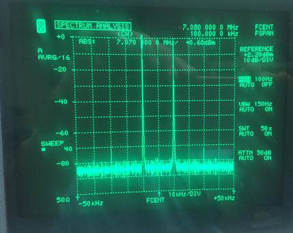
Left: My two tones setup (2 RF generators, RF Combiner) for 40m 7.070 and 7.090 MHZ +2.2 dBm each tone. The Third Order Intercept is minimum at +42.2 dBm. Right: LO at 10 MHZ at 0 dBm was applied to the board and the photo shows the RF+LO product at its IF output, terminated with the SNA-62 spectrum analyzer's 50 Ohms input. Please note that the DC bias was just set to 2.5V for both points and left there.
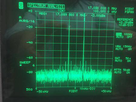
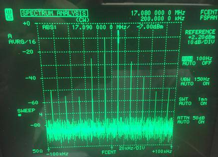
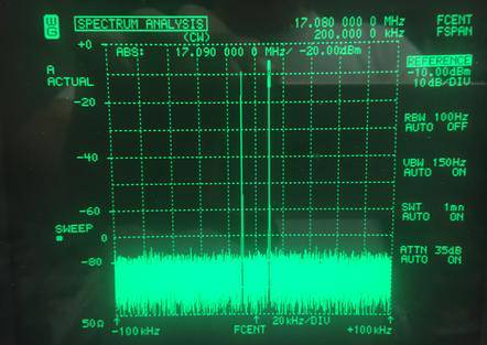
Left: Just for comparison, the FSA3157 mixer module was replaced with one SBL-1 doubly-balanced diode mixer. The LO power increased to +7 dBm and the frequency span of the spectrum analyzer doubled to 200 KHZ. You can see how "dirty" a SBL-1 can become at those power levels. Right: The two tones with reduced power in order not to overdrive the SBL-1 mixer. Of course it is unfair to compare a SBL-1 with an H-mode mixer. I just wanted to show how far is their distance. In a well designed system, the mixer can be protected from overloading and the overall performance can be made good (Elecraft K2 for example). On the other hand, one starting with better units can achieve better results easily.