


DRA-818VHF mini Transceiver Module
With Low-Pass Filter and Audio Amplifier
Just add a serial terminal and get on the air fast
Advancement in chip technology and DSP allowed so we can have a complete 1W VHF transceiver in a small module.
The absence of special crystal and mechanical filters, discriminator coils etc, allowed for reducing costs too.
The DRA-818V module is one example, made in China, costs under USD 15.00, take a look at its specs:
Frequency Range: 134~174MHz
Tx/Rx frequency independent, can be the same or at any difference
Channel spacing: 12.5 or 25KHz
Configurable multi-channels
Receiver Sensitivity: -122 dBm
Output power: +27/30dBm (high/low as selected)
CTCSS / CDCSS codes built-in
8 volume levels controlled from the UART interface
8 squelch levels controlled from the UART interface
Simple 9600N81 UART interface to control
Operating Temperature: -20°C ~+70°C
TX current: 450/750mA
Supply voltage: 3.3~4.5V (5V absolute maximum).
Working with some of these, I have seen that they need a low-pass filter to reduce harmonic content of the transmitted signal, an external audio amplifier to drive a speaker and other than that, just adding a PTT switch and a microphone makes a complete VHF radio. There is a High/Low selection pin for the transmitter power which when grounded reduces TX power by 3dB. There is a Power Down input I have never used, a PTT input (low to transmit), a MIC input, around 100 mV is ok, an AF output and a Squelch output which goes LOW when the receiver detects a signal. I have used that output to light an LED and activate (power-up from standby mode) the audio amplifier. This way the power consumption is kept low. I have checked that the squelch sensitivity is 1-2 dB close to the 12 dB SINAD sensitivity, if the squelch level is set to 1. Setting it to 0, the squelch is off continuously.
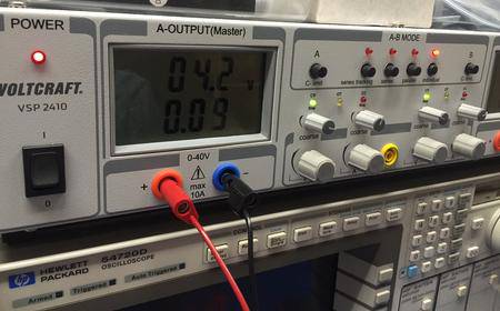
When in receive mode. it draws under 9 mA at 4.2 VDC (4.2V is a fully charged Li-Po battery). On transmit, the specified current is 750mA but I have seen 1.15A max in some of them, without reaching 30 dBm exactly.
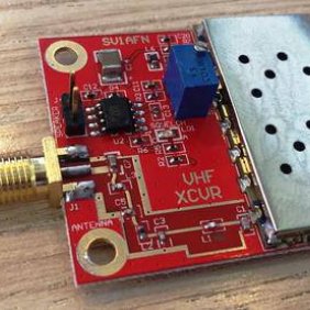
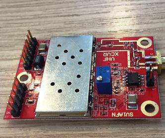
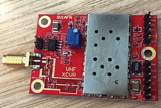
The PCB dimensions are 53 x 36.5 mm and it sure can be made smaller but I thought to place pin-headers for interfacing and some extra components like chokes and capacitors to control RFI.
The RF output power is not as specified. It is close but always less than 1W. The photo I posted here shows +28.5 dBm instead of +30 dBm. The Hi/Lo pin if left unconnected forces the transmitter to output its higher power and when held to ground the output power drops 3 dB.
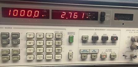
Although the receiver audio level is controlled via the UART in 8 levels and normally it does not need a volume control, I have included a small pot for adjusting the audio level more accurately if needed for a modem or APRS etc. The audio amplifier chip is the LM4871 and its gain is programmable with the external resistors. I have posted a photo of the distortion measurement at 1 KHZ at a high SINAD, is 2.76% max
The UHF version is the DRA-818U. It covers 400-470 MHZ. The PCB I have prepared is the same except the Low-Pass filter.
Its transmitter RF output power is less, around 0.5...0.65W on HIGH. I have talked with the manufacturer and they said it is "normal" (in Chinese...). Of course is not a big issue, but don't expect tight tolerances.
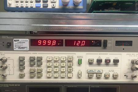
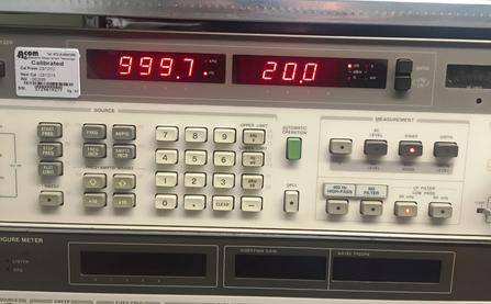
The RX sensitivity on the other hand, is as specified. I have posted photos here with sensitivity measurements both for 12 dB SINAD and 20 dB SINAD.
The figures are -124 and -122 dBm respectively.
The Module includes a high-quality ENIG FR4 PCB (53 x 36.5 mm) that comes with all SMD components factory pre-soldered.
RF capacitors are used for all the circuits. High Q inductors are used in the Low-Pass Filter section and high-current types for the RFI filters.
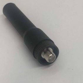
One SMA female connector - long shaft - is also supplied soldered. Washer and nut supplied.
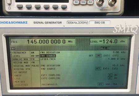
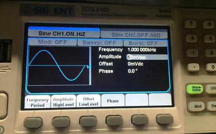
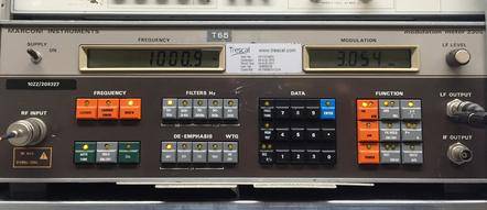
A 1 KHZ audio signal is applied to the MIC input, 70-100 mVpp is enough, the transmitter deviation is 3 KHZ as shown on the Modulation meter.
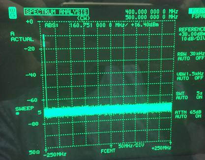
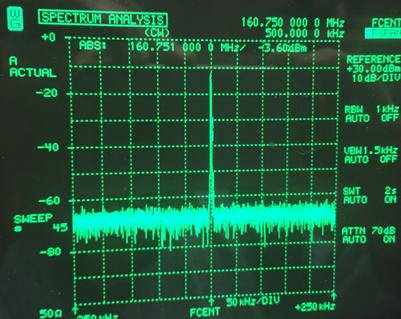
Spectrum measurements of the VHF transmitter's output: Close spurious not found (left), harmonics attenuation is greater than 65 dB (right).
Receiver Sensitivity: For 12 dB SINAD in the Agilent 8903B audio analyzer, -124 dBm of RF power input is needed, and for 20 dB SINAD, - 121 dBm power is needed. Setting the RF generator to -122 dBm, I have found the Squelch sensitivity. This was set to 1 before, through the UART interface.
Programming: Set your Arduino (UART levels should be 3.3V), or other MCU or a simple terminal software from your computer using a USB to Serial interface to 9600N81 and by sending AT+DMOSETGROUP=1,145.0000,145.0000,0000,0,0000 and (important) CR/LF at the end, the receiver will be tuned on 145.000 MHZ, the transmitter on 145.000 MHZ, the squelch will be set to off and the step to 25 KHZ.
The module will respond with a 0 if the command is accepted and with 1 if in error.
For more information on the programming, check the datasheet, available for downloading on this page.