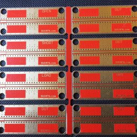
RF Experimenter's - VNA test PCBs (5 pcs) Un-soldered Connectors
With a 50 Ohm CPW over Ground Transmission Line and space for Thru/Load and DUT1-DUT3
Here is a complete KIT of 5 PCBs with a 50 Ohms Co-Planar Wave-Guide Over Ground Transmission Line and SMA connectors with space in the middle for user fabricated Load/Short/Open and DUT (Device Under Test).
An experimenter can place and test a DUT for RF performance or signal integrity.
The DUT can be virtually anything, from a small capacitor used for decoupling digital power lines to check its capacitance over applied voltage, over frequency or pulses to a more complicated passive or active circuit with 50 Ohms input and output ports. Even multiple capacitors in parallel, frequently used in RF or high-speed digital designs for DC rail decoupling can be placed and characterized by using a given methodology with DC voltage applied or not applied.
I would strongly suggest you to visit Dr Istvan Novak's website
http://www.electrical-integrity.com/
which contains excellent articles and information about signal and power integrity. Also about distributed power.
Today's high speed digital circuit design needs RF design knowledge and experience. It is really an interesting part of technology and subject of expert knowledge. Students, engineers and experimenters can benefit of this small and handy PCB Panel and use it as a tool for improving their own designs or realizations.
Don't think you also need an expensive VNA together. Although it is great to have one, there are a lot of measurements one can conduct using a multimeter, a phase detector like my AD8302 Module, a directional coupler, a power detector, a power supply, an oscilloscope and a pulse/signal generator. By not owning a VNA sometimes helps on finding different smart solutions to a problem.
The PCB material is FR4 so please don't expect great performance over 3-4 GHZ, but if your work is at lower frequencies, this panel suits most of your needs perfectly. For characterizing components for power distribution for example, you will work on 100 HZ or up to 10 MHZ or 100 MHZ max or about one decade over the series resonance frequency of the DUT.
In addition you get 11 pcs female SMA connectors (not soldered). We also offer a soldered connectors version of this product please check the products list.
REF https://passive-components.eu/pcb-fixtures-and-solder-wick-trick-to-improve-component-measurements/